
The minimum order quantity at JLCPCB is 5 pieces. To order Module17s you will need:
Gerber files define the board layout and overall design (holes, geometry etc.). A BOM lists all parts used in the device. The last file contains XY coordinates of every part listed in the BOM for automated placing.
Download all the files listed above. For each file, right click on the Raw button and select Save file as. When you are done, go to jlcpcb.com.
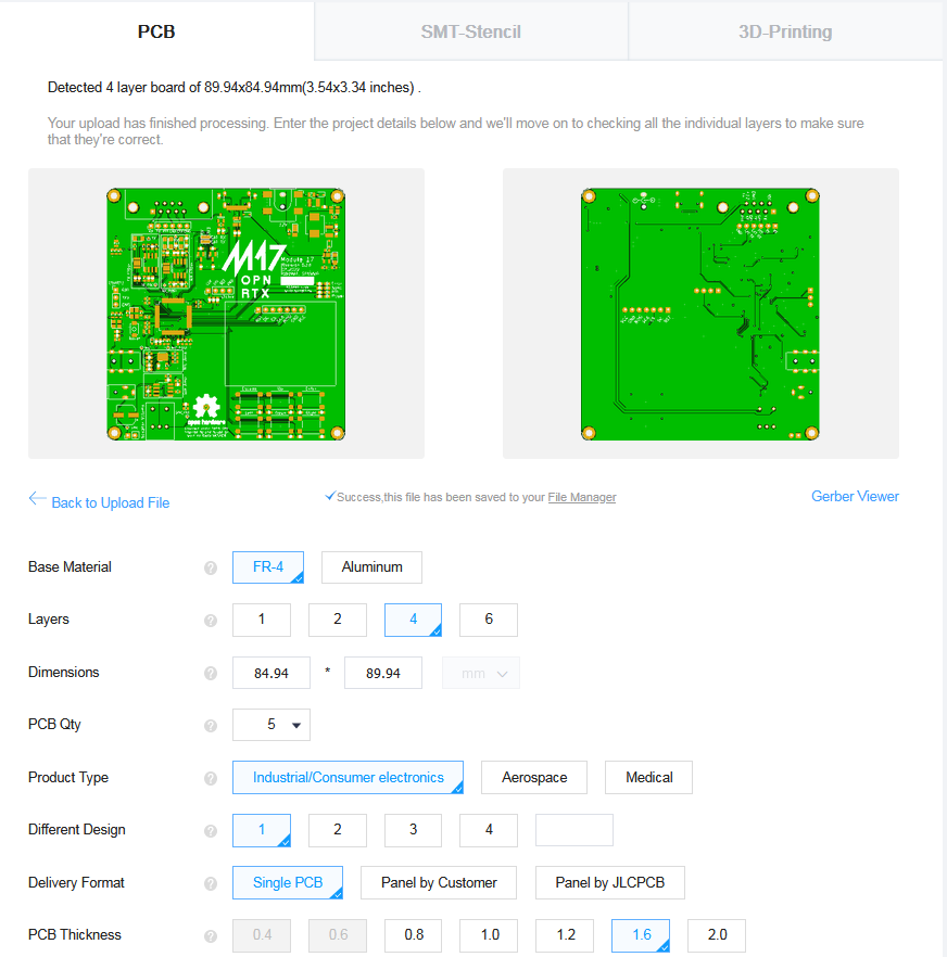
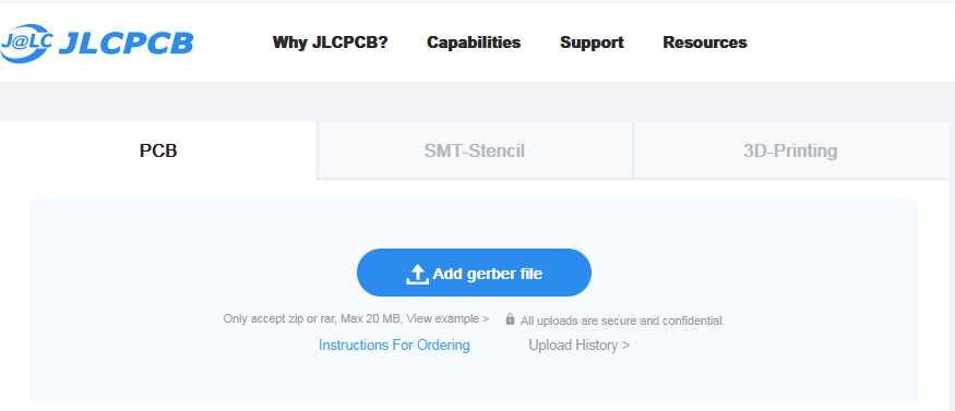 Upload zipped gerber files using the Add gerber file button. After the system is done processing your file, you should see that the board info has been updated.
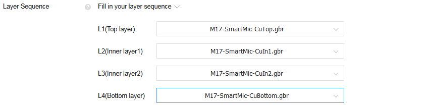
 The next step is to select correct copper layers to form the stack. Use the drop-down lists to set it exactly like in the image below. You can leave the rest of the settings with their default values.
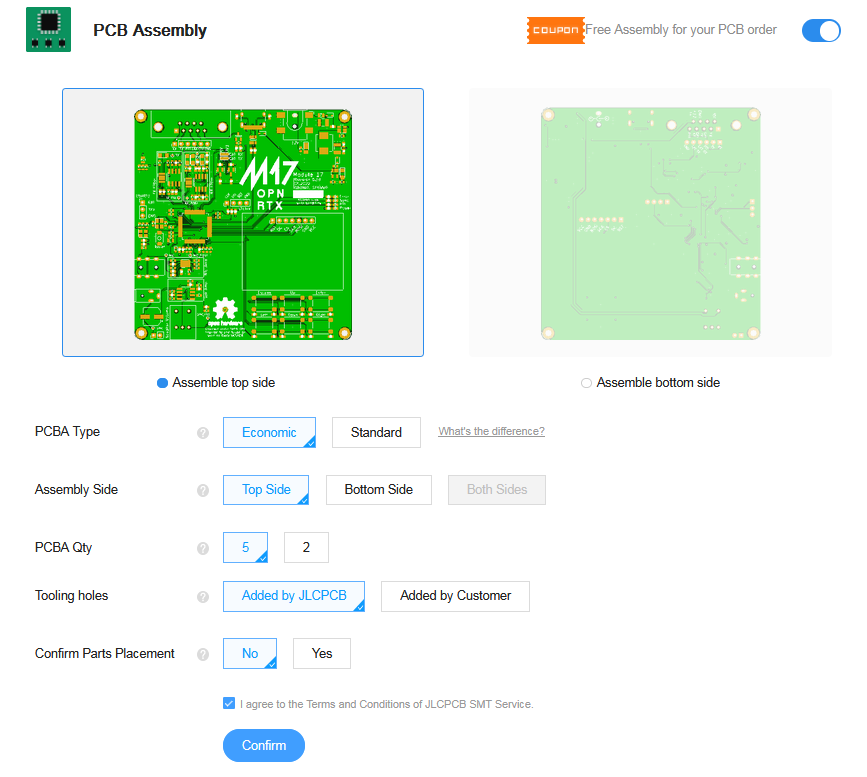
 Now it's time to set up the assembly process. Click the slide switch to start.
 Accept the default settings - we want JLCPCB to assemble the top side where all components are located.
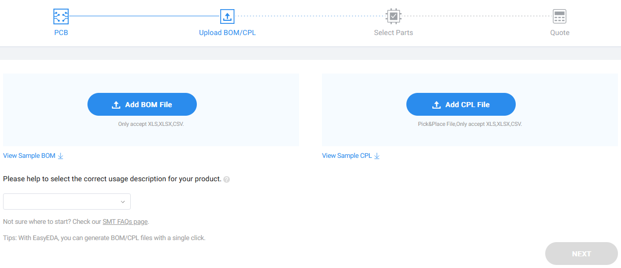
 After all the settings are confirmed, you will be asked to upload the BOM and pick-and-place files.
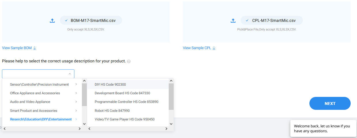
 Use the files downloaded from GitHub. CPL is how JLCPCB call our pick-and-place file. We recommend selecting the DIY category for the project. Proceed with Next.
 You should be presented with a long list of parts.
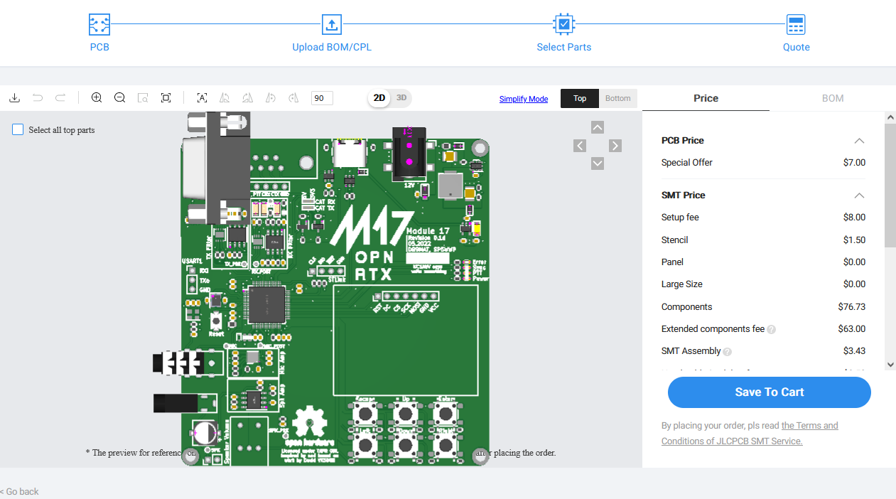
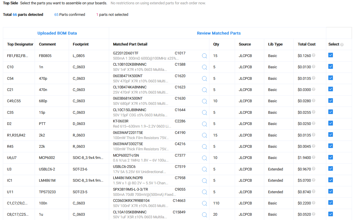 Ideally, no parts should be listed as part shortage. Click the Next button below the table. You should now see a 2D render of the board. Don't worry if THT parts are misaligned. In my case the DE9 connector was facing the wrong direction. Don't fret - those parts are assembled manually. After you are done playing with the 3D preview, press the Save to cart button.
 Proceed with the payment. This ends the JLCPCB part. Still, a handful of components has to be placed manually. Those parts are:
- OLED,
- volume potentiometer (logarithmic),
- 2 digital potentiometers
Let's start from the top - OLED. This part is manufactured by Waveshare and the module's name is Waveshare 1.3inch OLED Display Module. Use your favourite search engine to find those online. Volume pot is a little bit more tricky - the exact value that's used in Module17 might not be available. The schematic asks for a 50k logarithmic. Use any value in the 10..100k range, for example Bourns PTR901-2025F-A103. Note that the potentiometer should have a SPST switch built-in. Lastly - SMD digital potentiometers. There are 2 of them in the device - U8 and U9.